Object Selection & Information
All objects in the workspace contain information related to their geometry and position in the workspace. These properties are categorized as :
- General Properties - layer name, color, linetype etc.
- Geometric Properties - lengths, angles, radii, circumferences.
- Spatial Properties - their x-y-z location in the graphics editor.
- 3D Visualisation Properties - material properties, rendering styles etc.
An object's information is collected by selecting the object or group of objects, thereby applying Grips to critical vectors of the objects.
Information collected by selecting an object or group of objects is organized in the Properties palette or the Quick Properties palette. This information can be viewed and modified in real time, providing a quick and simple method of updating objects in the workspace. Some of the methods of accessing the information of objects is outlined below.
Quick Properties Palette
The properties listed above are displayed and modified using the Properties Palette or the Quick Properties Palette.
For example, the length and angle of a line can be modified when selected using Grips. The radius or diameter of a circle can be modified when selected with Grips and layer property changes can be done instantly. This is referred to as in-place modification.
Multiple objects can be selected and are added to the object drop-down menu in the Quick Properties Palette, so that changes can be done in a particular sequence, usually for design purposes.
Take Note
The Properties and Quick Properties palettes are displayed when selecting an object and using the right-click mouse button and selecting either from the context menu. These palettes can be docked at the edge of the editor if preferred.
In the example below, the circle is selected and the radius of the circle can be modified using the Quick Properties palette.

Circle selected; radius updated in the Quick Properties palette
Take Note
The Quick Properties palette cannot be used to change all objects. It is more frequently used to view the properties of an object. Circles, radii of arcs and simple line geometry can, however, be changed using this tool. For more complex geometry, the Properties palette is used.
Properties Palette
Annotation & Drafting | View | Palettes | Properties
The Properties palette is a context-sensitive feature that is used to change any physical (layer, color, linetype etc) or geometric (length, angle, radius etc) characteristic of an entity.
The properties of all objects in the editor can be viewed and updated using the Properties palette, including text, dimensions, hatch features and all line and circle geometry.
By selecting an object using grips, the Properties palette will be displayed containing pages of information specific to the selected object.
To select and modify an object using the grips, either double click or right click the object, then select Properties from the context menu.
The Properties palette is used extremely frequently and it is recommended that the palette remain docked at the side of the editor.
Example
In the example below, the Properties sheet is used to view and update the selected dimension.
In the illustration below, the dimension has been selected and its properties viewed in the Properties palette.

Properties palette used to view and change properties of the selected dimension
List and ID Functions
Information specific to a selected object can be obtained by inputting the instruction List into the command line. A quick analysis of the physical and geometric properties of the selected object can be viewed in the AutoCAD Text Window.
The ID command can be used to identify a physical point or a geographic coordinate in the workspace.
Using the 'ID' Instruction
Finding the coordinate of a point
This tool identifies the XYZ coordinate position of a point in the workspace.
When the coordinate system is set to Relative and the origin has been relocated, coordinate points are measured in relation to 0,0,0
The coordinate of a point is found by inputting ID into the command line and selecting the position shown by the pointer below.

Finding the coordinate position of a point using the ID command
Grips
Grip 'handles' are used to select an object or group of objects for quick and convenient in-place modification or manipulation purposes.
Grip handles are attached to an object when blue handles appear at strategic points of geometry on an object.
When the grip handle is selected and turns color, the short cut menu provides multiple modification options which can be selected. These options are also displayed on the command line and the enter or spacebar can be used to cycle through these options.
Grips are very useful for modifying dimensions and text and can be used to swiftly move blocks and other compound objects around the workspace.
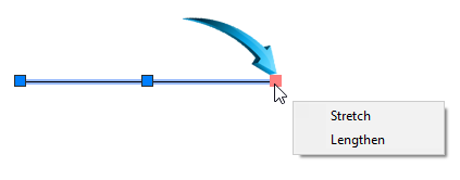
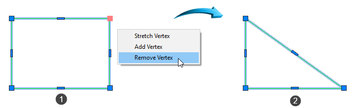
Grips are frequently used to add or delete a node by moving one grip handle onto another, shown below.
Grips are canceled using the keyboard Escape key.
The topic of Grips is discussed in more detail here.
Gizmo

3D Basics | Home | Selection
The Gizmo is a 3D context selector which is available when a part is rendered using a visual style such as Hidden. It allows objects to be moved, scaled and rotated directionally along the displayed axes.
The Gizmo works in conjunction with Grips, and commands are not required to be issued prior to selection.
When selected, the colors of the Gizmo axes correspond directly to the current UCSUser Coordinate System icon, shown below.
In the example below, a solid object is used to demonstrate the move, scale and rotate functions of the Gizmo.

Make sure the view is set to a 3D view such as Isometric South East, using the ViewCube. A rendered visual style is required. Select the part to attach the grips, shown below. By right-clicking within the frame of the Gizmo axes, the functions Move, Scale and Rotate can be selected, shown below right.

Using the Gizmo selector
In the example below, the Scale option is selected and proportional scaling is achieved by dragging the handle of the Z-axis upwards, shown below.
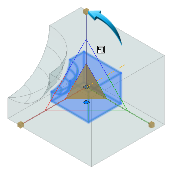
Increasing the scale of the part using the Gizmo
By right-clicking and selecting the Rotate option, a spherical shell is provided, allowing the part to be rotated about an axis. In the example below, the colors of the rotator shell correspond to the colors of the UCS, shown below left.
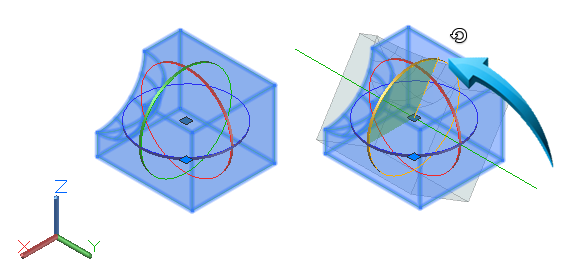
Rotating using the Gizmo
The Move option allows the part to be moved using the directional axis. In the example below, the part is moved negatively along the X axis

Moving using the Gizmo
Window /Crossing Selection
Objects can be selected by dragging a selection rectangle around or through the objects to be selected.
The direction of the selection rectangle dictates which objects will be selected.
A left-to-right selection direction is referred to as a window and only objects contained within the selection rectangle will be selected.
The left-to-right selection method can either be from top left to bottom right, or bottom left to top right, shown below. The selection area of the window is light blue, with a solid selection outline, shown below.

A right-to-left selection direction is referred to as a crossing and objects contained within and cut through by the selection rectangle will be selected.
The right-to-left selection method can either be from top right to bottom left, shown below, or bottom right to top left. The selection area of the window is light green, with a dashed line selection outline, shown below.

Objects which are selected using the window or crossing methods can only be manipulated or modified once they have been accepted using the keyboard enter or space bar keys.
Selection Sets
Objects are selected individually or by enclosing them in a selection rectangle referred to as a Window or Crossing.
Objects which are selected are first highlighted, then processed by the current command when the enter, spacebar or right click mouse button is used.
Before accepting the selected objects into the selection set, additional tools can be used to refine the selection by adding or removing objects from the currently selection set.
Add/Remove from Current Selection
Objects can be removed from the selection prior to completing the command by holding down the SHIFT keyboard key and left-clicking the object to remove from the selection. Objects are added back into the selection by releasing the SHIFT keyboard key and left-clicking on the required object.
Press Enter, Spacebar or use the right-click mouse button when the selection is complete.
Select Last
By inputting L into the command line or the dynamic input fields after a command is issued, the object which was most recently inserted into the workspace will be selected. For example, when drawing multiple lines, the last line which was drawn will be selected after issuing the L instruction after a command.
Select Previous
By inputting P into the command line or the dynamic input fields after a command is issued, the object which was most recently selected will be highlighted. For example, any previously selected objects will be highlighted after issuing the P instruction after a command.
Select by Fence
An open polygonal crossing selection, referred to as a Fence can be used to select non connected items, illustrated below. After issuing a command, the fence option is activate by inputting F into the command line.

Objects shown above right selected by Fence
Select Similar
This tool is located in the local (right click) menu after an object has been selected. Selecting the Select Similar option allows all like objects to be selected as part of the current selection set.
In the example below, the door shown by the pointer is selected. To select similar objects, right-click and select Select Similar from the context menu.

First window selected; other doors selected using Select Similar
SubObject Selection Filter
This selection option provides a Selection Filter when specific geometric features are available in the drawing. This option is useful for 3D design as the option to select vertices, edges and faces can be filtered.
Example
In the example below the 3D Basics menu is used and a Box is drawn in the workspace. The viewpoint is set to Isometric South East using the ViewCube, shown below.

By right-clicking in the workspace and selecting the SubObject Selection Filter, a list of geometric objects such as vertex, edge and face can be selected. In the example below, the Edge option is selected.

This allows objects to be captured by targeting their edges, similar to the illustration below.

Selecting Edges only
In the example below, the Face option is selected, allowing a solid to be captured by targeting the faces only.

Selecting faces only
Take Note
The keyboard CTRL key controls how objects are selected, including subobject filters. Hold down the keyboard CTRL key to switch between the selection options.
Spatial Information
Coordinates
Coordinate input is the method used to define spatial distances and geometric information in the workspace.
Polar coordinates are used to input Length and Angular measurements based on the coordinate position within a 360º circle.
The formula for supplying a polar coordinate is Length, Angle. These coordinates are based on positive measurements.
Rectangular coordinates are defined by positive or negative X-Y values. Rectangular coordinates are sometimes referred to as Cartesian coordinates.
Below is an example of Rectangular Coordinate input : (line traveling backwards (x) and downwards (y) @-10,-10
All examples below are demonstrated with the Dynamic Input Status Baroption deactivated.

Rectangular Coordinate input : @-10,-10
Below is an example of command input using Polar Coordinates using a line of 50 and an angle of 45, shown below.

Polar Coordinate input : @50<135
In both of the above illustrations, the coordinates were input as relative coordinates, shown by the @ symbol.
Absolute and Relative Coordinates
Absolute coordinates determine spatial distances based on the 0,0 origin position in the workspace.
All points drawn in the workspace are then referenced from this 0,0 base position.
The 0,0 base position is referred to as the Origin.
The origin can be relocated to any position in the workspace by selecting the origin, right-clicking and selecting Move Origin Only. The X-Y origin can now be moved to a new position in the workspace.

Moving X-Y origin
The origin is restored to its original position by right-clicking onto the node shown above, and select the World option.
When using Command Line input, an absolute coordinate is given as Length and Angle, shown below.
Coordinate Input
Coordinate input to determine distances and angles can either be input into the command lines or the dynamic input fields.
When inputting spatial values into the dynamic input fields, the TAB keyboard key is used to access these fields and to cycle between then until the correct value is input.
In the example below, a line with a length of 50 and an angle of 45° is drawn by inputting these values into the dynamic input fields.

Using the dynamic input fields to input a length of 50 and an angle of 45°
When inputting the same value into the command line, the value @50<45 is used to determine the length, then the angle values, shown below.

Using the command line to input a length of 50 and an angle of 45°
Ortho Mode
When Ortho mode is activated in the status bar or by using the F8 function key, the movement of the cursor is locked into strictly polar angle (0, 90, 180, 360 degree movement)
When inputting coordinates when ortho mode is activated, the distance or length value only is required, providing the placement of the cursor is in the direction of the intended angle, shown below.

Distance/Length value only needed when ortho mode (F8) is activated
Similarly, when using command line input, only the distance or length value is required when the placement of the cursor is in the direction of the intended angle, shown below.

Length value only required when ortho mode (F8) is activated
Polar Tracking
Restrict Cursor to Specific Angles
When polar tracking is activated in the status bar or by using the F10 function key, the distance or length value only is required when inputting coordinates, providing the angle tracking is positioned in the intended angular direction shown below.

Distance/Length value only needed when polar mode is activated
Similarly, when using command line input, only the distance or length value is required when the placement of the cursor tracks to the intended increment angle, shown below.

Distance/Length value only needed when polar mode is activated and cursor tracks to intended angle
Tracking Angles
Tracking angles are accessed by selecting the Polar Tracking tool on the Status bar, shown below.

Tracking Angles
This tool provides the standard tracking angles with the option to set a specific angle by selecting Tracking Settings and inputting the new angle into the Increment Angle field, shown below.
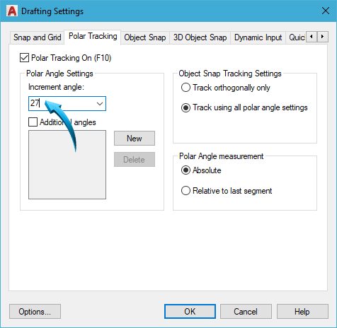
Setting a new increment (tracking) angle
Measurement Tools
Distance, Perimeter and Area
Drawing & Annotation | Home | Utilities | Measure | Distance

This tool finds the linear distance between 2 or more points.
This tool traces the points indicated and presents the information in the Measurement page of the Measurement Palette.
When finding the distance between 2 points, the Measurement Palette will provide both the linear distance (length) and the angle.
Example
In the example below, the distance is measured around the perimeter of the object, shown by the bold outline.

DISTANCE of red bold outline is measured. Result is 90
Return to the first point and press Enter. The command line has added the sequence of numbers and presented the total distance in the last line, eg: Distance = 90.
In the Example below, the Distance tool is used to find the area shown in the bold outline, below. This is done by inputting AR into the command line after the Distance command has been selected.
Select the DistanceDrawing and Annotation | Home | Measure | Distance tool, then select a point at the lower left of the object. Input M to indicate multiple points, then use the snap modes to snap to each successive point around the bold line.

AREA of red bold outline is measured. Result is shown above.
Angle
Drawing & Annotation | Home | Utilities | Measure | Angle
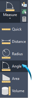
Finds the angle between any 2 points or the vertex angle between any 2 entities such as a circle, arc or line.
The Distance tool can be used to find the angle between 2 vertices.
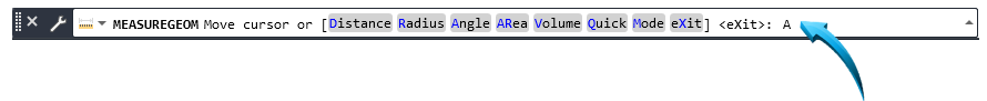
In the example below, the angle between points 1 and 2 is measured using the Angle tool. Select the Angle tool from the Measurement menu panel, then press enter to confirm that the angle will be measured between 2 vertices.
Use the Angle tool to measure the angle of the 3 vertices, starting at the top vertex, shown below right.

Angle tool used to measure the angle between 3 vertices
Tip
The Angle tool can be used to find the angular distance between the 2 end vertices of an arc, shown below

Use the Distance tool to measure the angle between the 3 points shown below.

ANGLE tool used to measure between 3 vertices
Radius
Drawing & Annotation | Home | Utilities | Measure | Radius

Finds the radius of a non-dimensioned arc or circle, shown below.

Quick
Drawing & Annotation | Home | Utilities | Measure | Quick
This command provides quick access to all the measurement tools, with the options being presented in the command line. In the example below, the Area option is selected, shown by the pointer below.
Selecting the Area option from the Quick measurement tool
Volume

Measures the volume of a solid object such as a box, cone etc.
In the example below, the volume is found for the cone.

Volume shown by the pointer in the command history
Add/Remove
Each measurement tool above allows the addition or subtraction of regions. In the example below, the Area measurement tool is selected with the option to Add additional areas. Regions 1 and 2 are selected and the total area is shown in the command history, shown by the pointer below.

Adding regions 1 and 2 to find the total area
 Back to Top